Fitting a Geometry on the DHR/AR
To install the Smart Swap™ geometry on the DHR/AR:
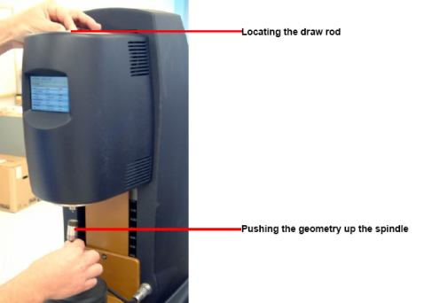
- Switch on the air and remove the bearing clamp by turning the draw rod counterclockwise (anti-clockwise). Refer to the figure below for draw rod location.
- Power on the instrument and allow it to initialize (about 30 seconds to 1 minute).
- Push the geometry up the spindle and hold it while locating the draw rod in the screw thread of the geometry.
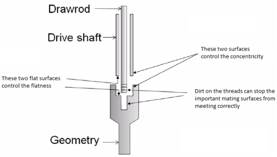
- NOTE: Visible run-out, or wobble, of geometries as they are slowly rotated on the drive shaft is generally caused by dirt on the mating surfaces. If you believe there is a problem with run-out, remove the geometry and clean the surfaces.
-
Screw the draw rod upwards (clockwise). It should be screwed finger tight but not forced.
To remove the geometry, perform this operation in reverse.
To install the geometry so that it is in the same position each time:
- Move the motor shaft to the home position by holding the Lock button for 3 seconds until you hear a short beep. Alternatively, click the Go to Home Position in TRIOS software.
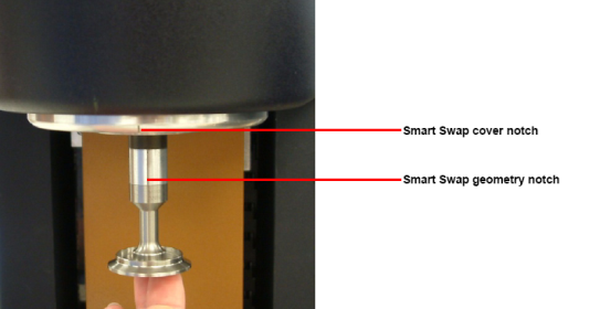
- Align the notch on the Smart Swap geometry with the notch on the Smart Swap cover and screw in the draw rod.
Back to to
